University of Southern California
Multi-agent Coordination with UAV and Ground Robots
Paper
Mars Forerunner: A Prototype for Coordinating Autonomous Exploration Between UAVs and Ground Rovers
University of Southern California, December 2020
Background
In this work, we develop a prototype for coordinating autonomous exploration between UAVs and ground rovers. Our project was motivated by NASA’s Mars Helicopter, which was developed with the ambitions to eventually test unmanned aerial vehicles (UAVs) in support roles (e.g. scouting routes) for ground rovers in future Mars missions, or even serve as standalone mission payload carriers. The project is composed of two main parts: (1) UAV mapping, and (2) rover pathfinding and navigation. In part (1), a UAV uses LIDAR to map out an area from a safe altitude, and to denote the obstacles and open space. In part (2), a ground rover utilizes the map provided by the UAV in part (1) to plan a path and navigate to several regions of interest, and then return to base. Practically, this application can be used for remote exploration in inhospitable environments: for example, on the surface of Mars or the moon.
Video
Problem Definition
For purposes of an initial prototype, our simulation assumes that this mission is carried out on flat terrain with regions of varied complexity in geological obstacles. Our UAV will travel to a series of coordinates that represent scientific regions of interest. The UAV will need to reliably map the area it travels to provide the ground rover with the ability to safely navigate to the region of interest. The ground rover should be able to use the map generated by the UAV in order to plan an obstacle-free path and navigate safely to each of the scientific regions of interest scouted by the UAV. General specifications that needed to be followed to accomplish these goals are listed below. Through iteration on our solution, we were able to come up with ideal values for linear and angular velocities, and a safe and smooth lookahead distance for the rover.
Technical Setup
To work within a simulated environment, we loaded a virtual machine running Ubuntu 16.04 with ROS Kinetic and Gazebo 7. We used MATLAB 2020b with the ROS and Robotics Toolboxes to communicate and operate the robots in the simulation environment. To simulate our design, we modified an environment with obstacles based on a MathWorks created world for a quadcopter simulation, and a representation for each of the robots. The obstacle layout was modified to increase with complexity for each successive waypoint. To represent the Mars Helicopter, we used the quadrotor UAV from this provided world and equipped it with a 3D LIDAR sensor, the Velodyne VLP-16. The ground rover is represented by the Turtlebot3, a popular and highly supported robot to work with in ROS and Gazebo.
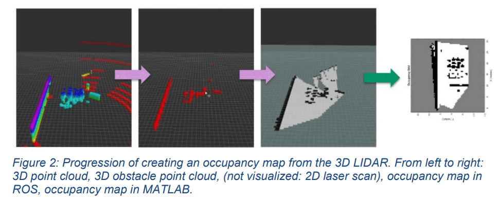
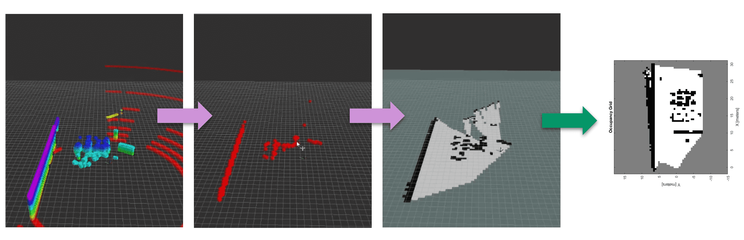
The mapping stack utilizes Hector SLAM to localize and generate a map of its environment. In order to successfully utilize 3D LIDAR, several steps were needed to reach the desired generation of a 2D occupancy map, as shown in Figure 2. First, the 3D point cloud of the LIDAR needed to be filtered against a height map algorithm to detect obstacles and remove unnecessary detections of the ground. Second (not visualized in the figure), the 3D obstacle point cloud was converted to a 2D point cloud using the pointcloud_to_laserscan ROS module in order to interface with Hector SLAM. Finally, the map data generated by Hector SLAM is published to a ROS topic for consumption in MATLAB as an occupancy map.
The binary array of map data received from the UAV in Stage 1 is converted into an occupancy map object, which is used to plan a path for the rover. The path planning algorithm used here is A* search, which will find the shortest path to the given goal point. Given starting and ending coordinates, a path is planned between the two, and a set of intermediate waypoints is outputted. Stringing these points together yields a path. In order to successfully plan a path for the ground rover, a transformation between the coordinate system of the robot’s simulation environment and that of the discrete map of the A* planner needed to be derived. This transformation considered the differing origin points, map resolution, and orientation of the axes.